Breakthrough on the MIDI synth

Ok, not quite. the wall i hit was i do not, or did not, at all understand how audio samples work, but now, i have learned what/how they are, how they can be passed to a super fast PWM drive or a DAC to produce audio (i have a nice audio-grade DAC so i may make the synth esp8266 or 32 based so you can add drum beats and other stuff via an app or web interface).

Now i know, and am currently learning how sample-tables work, as that is apparently important, if you want to output something more than just pure square wave. But thats just gravy and inconsequential, as it stands i know all i need to know to finish this thing, and shall, once i finish working on a newer, more important project with an immediate deadline, im making a WS2812B strip audio-reactive driver to drive a huge LED array.

Im back (again)

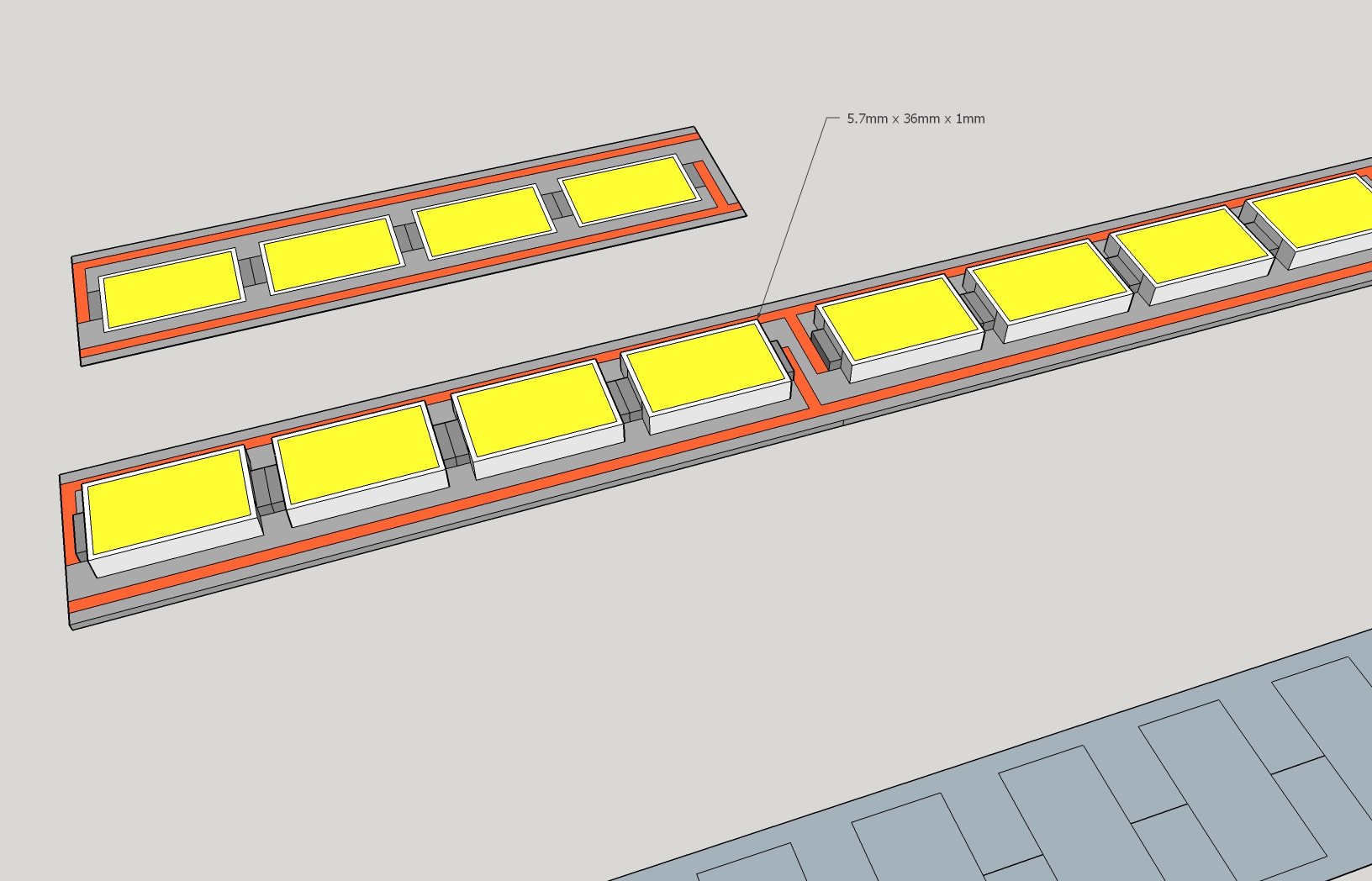
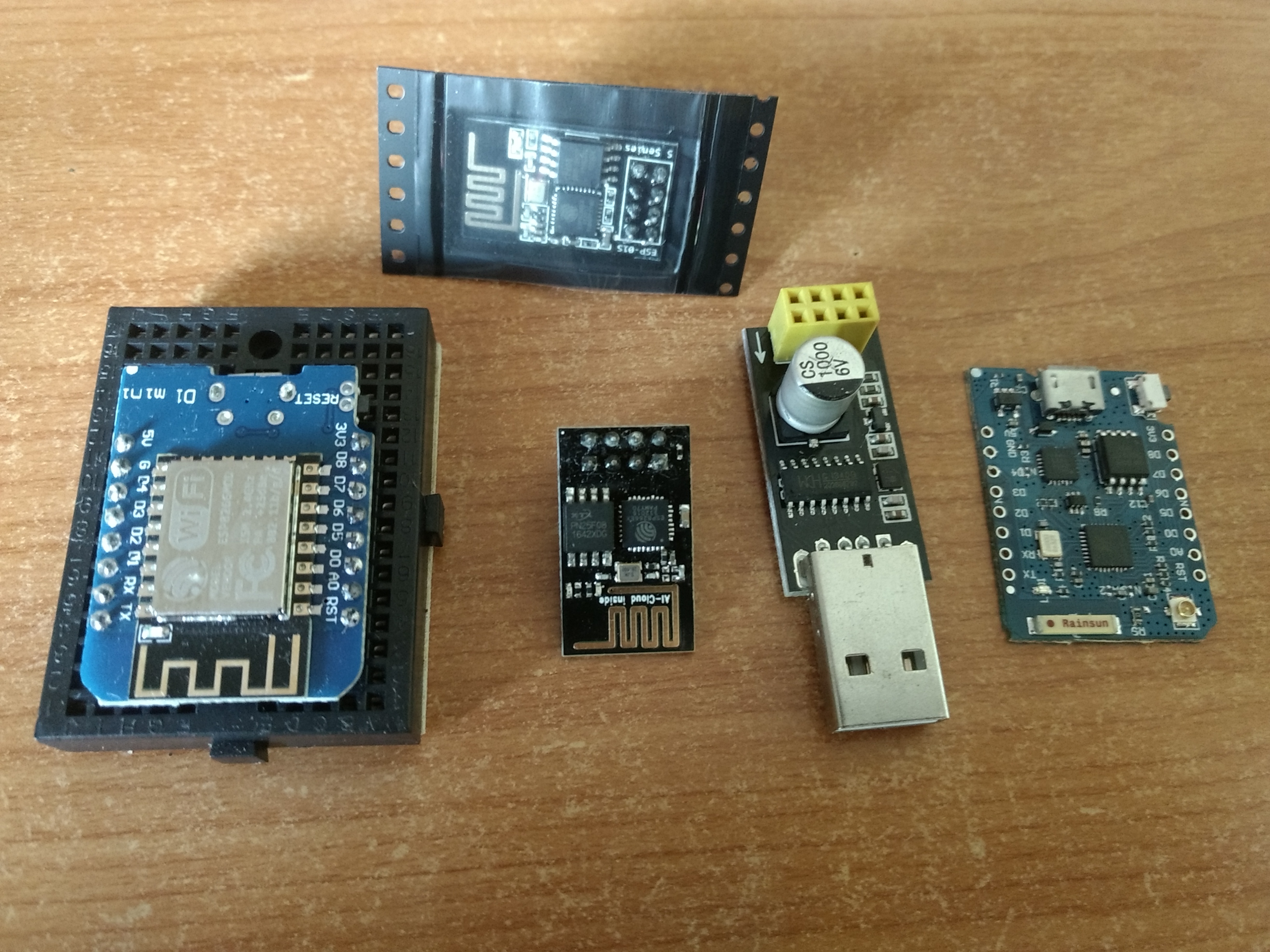
I have been very busy, with moving, changing to a new campus, besides also studying. I plan to very soon finish the backlight driver, ill also make some revisions, namely, adding the ability to use ANY microcontroller for this. Specifically ill make it compatible with the ESP8266 series which are capable of reading a signal voltage and outputting PWM. The ESP8266 is a wifi board, but we wont be making use of that (but just for kicks i might add a web interface someday), its stupidly fast, its only $2, and most importantly, not only does it have a built in USB interface, you can even program the damn thing over the air, meaning if you ever, or i ever, find a bug in the code, you simply can just upload a patched version without having to open the monitor, you can set up the thing to act as a hotspot for situations like this.

Just to clarify, the reason this thing seems too good to be true is because it is. the ESP8266 is fundamentally designed to work like an adaptor but wemos and nodemcu have made expanded boards that fully use all the chips GPIOs, which arent actually many.  Can do some pretty intense processing, relatively speaking, though usually not while using wifi, also the wifi code usually takes up most of the space on board, usually when running solo, its digitally connected (not analog) to 1-wire or SPI protocol devices that make use of the fact it can only handle 2-3 data connections, for digital sensors and such. Unlike the STM32F1 Bluepill which can, though its strengths lie elsewhere.

Anyway, what we are asking of this board is trivial.

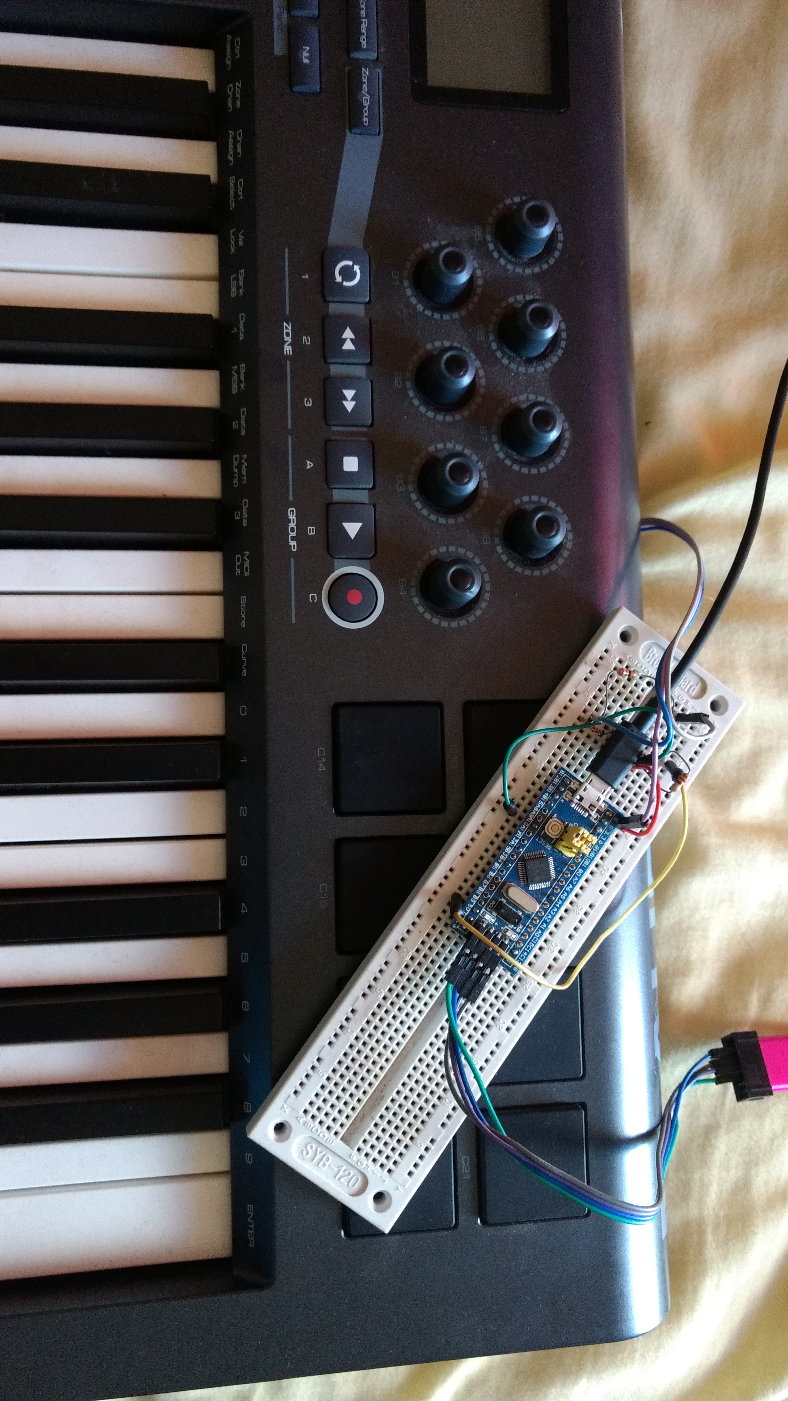
The reason i initially used the STM32 bluepill was i assumed i had to be able to accurately read a 600Hz PWM signal while also outputting a 10-20KHz PWM signal. this is something that is not easily done on an ESP. Also at the time the ESP cost twice as much.
Turns out though all you need is a single PWM peripheral running and use of the ADC to read the voltage. technically the STM32 is still better because itle read up to 5v, while the ESP only 3.3v, but, if you buy some 1% error tolerance resistors or better for the voltage divider, the issue will be moot, especially if i eventually manage to make a self callibration process, for which, it will be vastly better to be using the ESP, since you wont have to open the monitor again to add the program, hell, you can manually callibrate it from a web browser even, to  tell it what voltage is minimum brightness and what voltage is maximum, or you can just do all your brightness controlls through a browser too and totally ignore the need for any special interfacing, given the complexity of the OSD, this might actually work out better XD

Purely because using an external programmer can be a burden to beginners, and the ESP is now more supported than STM boards, and cheaper, ill switch this projects suport over to that. Anything though the ESP can run, can also be run on almost any other arduino too.

On a final note, to anyone posting comments, i get like 50 spam messages a week, if you want to share a link, break up your links or remove the http:// part, most websites trip my shitty spam checker. comments shouldnt need manual approval so feel free to double, tripple or etc post your questions until they pass, be sure not to use any rude language either. I dont mind if you have to post a bunch of times to make it come through. As a general rule, i think theres a pretty short list of safe websites so, just dont use any valid URLs in comments. also, dont add your website like it asks, thats a trap, i will change the user interface  to display an image saying “do not type anything in this bar, or your comment will automatically be deleted”, the spam bots always fill out random shit for the website url.

Feel free to say hello on my discord, i get mobile notifications from my server.

Backlight driver code is done and ready to implement

But just for testing purposes, it might work fine as is, or it might jitter a little and constantly turn the brightness up and down, i havent yet implemented anything for stabilizing the output.

right now this code doesnt adjust the output at all, ill edit it later though so it does. But it is both reading and writing PWM signals, all that needs to be done is some quick math to set the output brightness value (0-1024)  to the PWM percentage of that, and do this only once every few seconds, furthermore, to ignore slight shifts in the brightness, or some other method for stabilizing the output.


Continue reading Backlight driver code is done and ready to implement

I havent quit yet, but sorry about the wait

I recently begun an apprenticeship and finished a term of university at the same time so ive been smashed. Also i finally started drawing seriously, so, thats pretty much where my free time has been going.

Probably over this weekend im going to open my wacom again, however, i will be only doing 2 things. 1; adding extension cables from the backlight driver cable, to one of the cable areas for easy access later and so i dont have to dismantle the monitor again. the driver will be outside however, so, i guess i WILL dismantle it again, but, i wont need to any time soon.
2; I forgot to plug the USB hub back in 😛
So, cant use my usb port on the monitor, which has proven annoying.

Beforehand i might have a look at some new strips i bought, if they have the same power and less yellowing, i might switch them out. Otherwise, i can live with what i have now, i probably wouldnt even notice if i didnt have a perfect colored LED monitor right next to this one.

Im going to build a high powered custom LED strip for the wacom and anything else

Ive drawn up a model of the LED strip i have in mind. It is based on a 5.7mm long SMD LEDs, prefferebly 5736’s, but they arent too common, i may have to go with 5730s. I was going to go with the 5050s, or another LED but packed tighter, however, 5050s are a tad bit too big for the rails without going into multi layer PCBs which are just insanely expensive. I was also going to go with packing heaps of LEDs on the strip by turning them sideways, but, same reason, i couldnt, so ultimately this will end up being a modular larger version of the exact same strip. not that its bad or anything. this strip though will utilize parallel series of 4 instead of 3, meaning it can be safely run at 12v unregulated.

Continue reading Im going to build a high powered custom LED strip for the wacom and anything else

STM32 based MIDI synth

I realized the STM32F103C i have has a pretty high clock speed, so currently im trying to turn it into a basic FM oscillator synth. In other words, it will read midi input from another device, like piano, midi controller, etc, then convert it into sound.

I am using this library https://github.com/FortySevenEffects/arduino_midi_library , its as its described, basically plug’n’play, though there is a small number of tweaks and understanding to utilize this as i have found, not just for the stm32, but any board you use this with, less so though for the UNO R3

Continue reading STM32 based MIDI synth

Raw Monitor dissasembly and backlight installation videos now available

Heres the video links
Part 3 (working and comparison with real LED backlit display): https://mega.nz/#!jF4RSL5I!bn4SK65uxBnkQVmOyDXK4VzoAqdwQ_i6XemXYzvP9bc
im still working on editing a proper one to put on youtube.
It would be substantially edited down, annotated and include several photos i took during the recording to show how to do some of the trickier parts.